Nature of the task
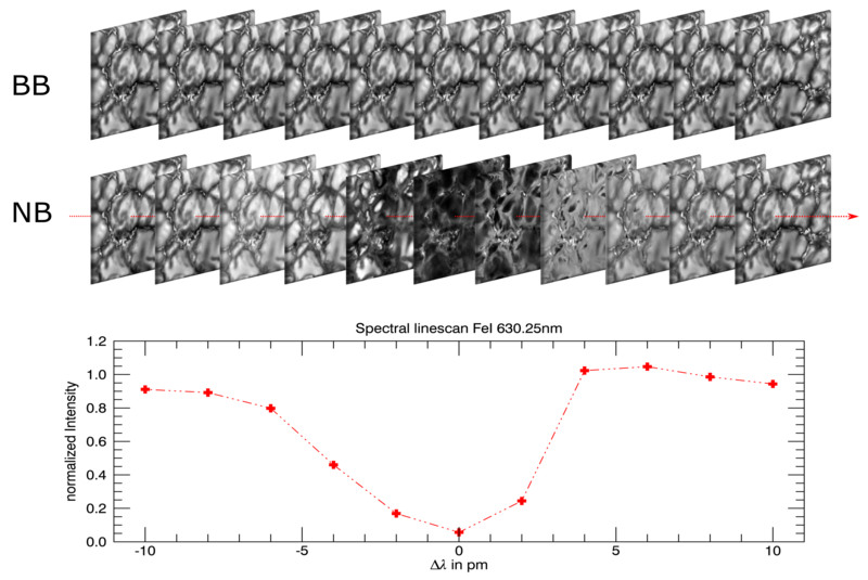
Functional principle of 2D spectroscopy: With the aid of a narrow band (NB = narrow band), tunable optical filter, successive images of the sun are taken at different wavelengths in the area of solar absorption lines. The 3-dimensional data set obtained in this way is represented in the figure by the NB image series. Since the residual intensity in the line core of solar spectral lines originates predominantly from higher regions of the solar atmosphere, not only the intensity changes but also the structure of the observed regions in the region of the line core.
This 3D data set thus contains the full spectral information for each image point, as shown in the figure for one image point along the red arrow. Simultaneously to the narrowband NB measurements, images are obtained in the spectrally neighbouring continuum. These are used as context data and for image reconstruction. For the investigation of magnetic fields with VTF, the NB channel is split again so that the light is recorded separately but simultaneously with mutually orthogonal polarisation states. (Figure: M. Schubert/VTF/KIS using MHD simulations by M. Rempel (NCAR/HAO) and J.M. Borrero (KIS))
The Visible Tunable Filter is designed to generate images of the sun's surface in a narrowly defined, tunable range of the spectrum with the highest spatial resolution. This resolution is made possible by DKIST. The instrument is used to scan absorption lines to enable precise imaging spectroscopy, spectro-polarimetry and photometry of the solar surface. The observations are used to obtain, in rapid succession, two-dimensional maps of line-of-sight velocity as well as of the magnetic field vector of the dynamic plasma. This enables researchers to study the evolution of solar structures on scales between 20,000 and 40,000 km in high cadence.
Functional principle
The centrepiece of VTF is a tunable optical filter that makes it possible to take images of the sun in a very narrow wavelength range of around 6 pm which is the range referred to as filter width or spectral resolution. The passband of the filter (i.e. the colour of the solar spectrum that can pass through the filter) can be adjusted in the visible solar spectrum from red (870 nm) to green-blue (520 nm) and can then be gradually adjusted (spectrally) in very small steps of a few picometres. One nanometre is equivalent to one billionth of a metre (1 nm = 10-9m), one picometre to one trillionth of a metre (1 pm = 10-12m). The smallest atom - hydrogen - has a diameter of around 50 pm.
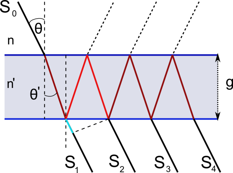
In VTF, two Fabry-Perot interferometers (FPI, also known as etalons) are used as adjustable filters. These are based on the principle of multi-beam interference. Two glass panels are mounted in parallel and their inner surface is covered with a partially reflective layer. Broadband (white) light entering the gap between the glass plates is reflected back and forth several times until it emerges again, as the plates are only partially reflective. Figure 2 schematically shows the multi-beam interference. The emerging waves overlap and this is referred to as destructive interference if, depending on the light wavelength and the width of the slit, a wave crest meets a wave trough of the overlapping light waves. If, on the contrary, crests meet crests and, accordingly, the troughs meet troughs so that they reinforce ane another, this is known as constructive interference. By adjusting the slit, it is therefore possible to determine which light of a specific wavelength passes through the filter and can be detected. The conditions for constructive interference are repeated periodically as a function of light wavelength and plate distance. In order to allow for the etalon to be used as a narrowband filter, it is therefore necessary to isolate one of these passbands. This is achieved by combining several such filters with different widths and different distances between the periodically repeating pass areas. In the case of VTF, two FPIs and one of the filters referred to as interference filter are combined. Figure 3 shows this based on the respective transmission profiles and overall profile.
Design


VTF has a volume of around 4 m x 3 m horizontally and 6 m vertically. The lower part is located below the instrument platform of the DKIST-Coudé laboratory. The light reaches the instrument as a parallel (collimated) beam. A camera lens generates a first focal plane (F1) which houses an aperture wheel with field and calibration apertures.
This is followed by another wheel with narrowband filters for selecting different spectral ranges, followed by a modulator for the polarisation state of the light. The monochromator consists of two etalons, which are arranged near an intermediate focal plane (F2) (‘telecentric setup’). Another image creates the final focal plane. Here, a polarising beam splitter splits the light so that two cameras can simultaneously record filtergrams of orthogonal polarisation states (linearly or circularly polarised, depending on the modulator position).
Behind the aperture wheel in F1, around 10 % of the incident light are decoupled for context shots by a beam splitter for a channel referred to as broadband channel. Broadband filters are used here to record images in the neighbouring continuum of the spectral line under investigation for each narrowband filtergram recorded. These images are also used to reconstruct the narrowband filtergrams and to determine horizontal movements in the observed image field.
Optical design
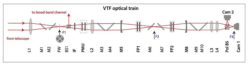
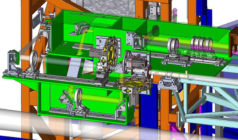
The entire optical setup of the VTF comprises 50 optical elements, some of which are made up of several components, such as the modulator or the two etalons. The simplified linear representation shows the optical imaging in the main optical path with a parallel (collimated) beam coming from the telescope. From this beam, the VTF imaging lens L1 generates a first intermediate image on plane F1. Previously, the bundle is folded once by the deflecting mirrors M1/M2. A large number of components for analysing the light and for calibration are located around F1. This area is referred to as the F1 unit. The F1 unit is also where around 10 % of the light for the broadband or context channel are decoupled via a beam splitter. In the filtergram or narrowband channel, the beam is then collimated once more by L2 and deflected laterally and downwards by M3 and M4. The camera mirror M5 then forms another intermediate F2 image. The etalons lie close to F2 in the vertical beam folded by M6 and M7. After passing through the etalons, M8 collimates the beam again, which is then deflected by M9 and M10 back into the vicinity of the F1 unit. The etalons are located near F2 in the vertical beam folded by M6 and M7. After passing through the etalons, M8 collimates the beam again, which is then redirected by M9 and M10 back into the vicinity of the F1 unit. Lenses L3 and L4 then reproduce the solar image in the desired scaling onto cameras 1 and 2. Orthogonal polarisation states of the light are separated in front of the cameras with the aid of a polarising beam splitter. If no magnetic fields are being analysed, the beam splitter is replaced by a glass block and only one camera is read out. The context channel is read out by the 3rd VTF camera. The 3D illustrations of the optical design (below) show not only the folded narrowband channel but also the decoupled part of the broadband channel. Not included are various monitoring units for checking the alignment.
Mechanical design
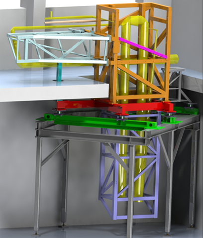
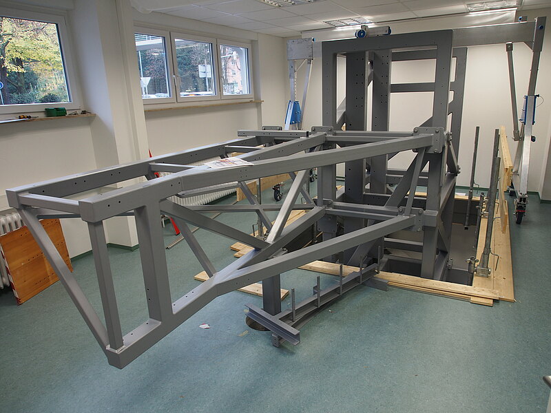
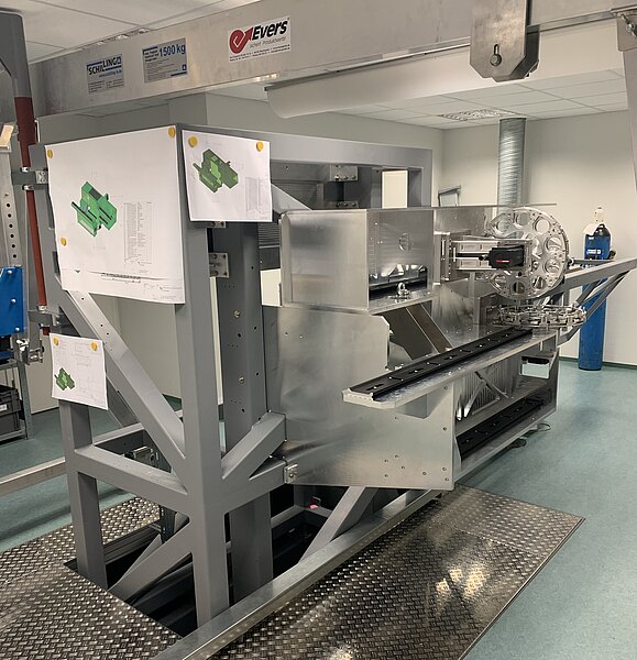
Modular design of the VTF support structure in the installation position at KIS laboratory
The individual welded modules are shown in different colours. The red horizontal main frame represents the interface to the laboratory and to the two vertical modules above and below it. In order to assemble the VTF structure at KIS, the part of the DKIST Coudé structure into which VTF was going to be integrated was replicated (shown in grey). The green beams were attached to the Coudé structure and specially adapted for VTF. Duplicates of these beams and the flanges attached to them have already been installed at DKIST and aligned exactly as at KIS laboratory. The heaviest individual module weighs 800 kg, the entire structure around 2.4 tons.
In order to be able to completely set up VTF at KIS in a specially rented building, a breakthrough was made from the ground floor to the subjacent basement and ventilation and air-conditioning systems were installed. At DKIST, the main frame is located just above the laboratory floor and VTF protrudes higher in the actual laboratory. (Figure: Th. Scheiffelen/VTF/KIS)
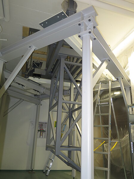
Due to the extensive 3D structure of the VTF optical design, the instrument could not be set up as a classic ‘breadboard instrument’ on a horizontal optical bench. In addition to providing stable and secure accommodation and arrangement for the optical assemblies, the support structure had to also allow for the laboratory floor to penetrate into the area below. At the same time, the entire structure had to remain transportable and had to allow for the structure to be fitted and assembled both at KIS and DKIST laboratories. The structure and all other components had to be designed to withstand strong earthquakes that are possible on Maui. The first natural frequency of all components had to be above 10 Hz.
Several structural and assembly concepts were evaluated for VTF. The final concept consisted in a modular welded steel-girder structure fixed to the mounting plates which, in turn, support a rail system on which the smaller optical units were mounted. The steel structures were welded manually, achieving a dimensional accuracy of approx. 1 mm in the longest diagonal of approx. 6 metres. The flange surfaces of the horizontal main frame (base frame), which forms the interface to the laboratory and to which also the vertical frame modules connect, were machined to an accuracy superior to 1/10 mm. The structure was designed in such a way that its installation at the narrowest point was possible with just a few millimetres of clearance at KIS laboratory. The space available at DKIST is somewhat more generous.
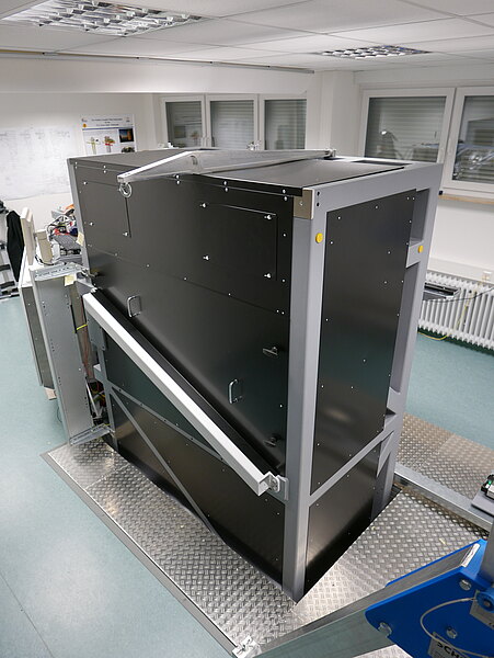
In order to accommodate the etalon, a special etalon compartment was integrated into the steel structure which, among other things, carries a breadboard mounted on heavy-duty pull-outs. The breadboard can be extended to mount the etalons. During operation, the heavy-duty pull-outs are fixed. The breadboard can either be permanently attached or, if necessary, supported by earthquake-proof dampers.
The entire vertical part of the instrument is covered, providing the etalon compartment with additional protecting against draughts.
The console referred to as F1 is the support structure for a large number of units that are located near the F1 focus. The three VTF data cameras are also mounted on this support structure. Parts of the F1 console are covered for safety reasons and to darken sensitive areas from stray light. The F1 console itself is attached directly to the vertical upper frame module.
Optomechanics


The optics of VTF are grouped into 40 units. In total, the optomechanics consist of more than 300 axles, all of which are precisely specified and adjustable and 41 of which are electrically driven. Strictly speaking, a distinction must therefore be made between purely mechanical assemblies (such as support structures, dimming and mounting aids), purely opto-mechanical assemblies (OM) and opto-mechatronic assemblies (OME).
The mechanics work package was by far the most comprehensive work package of VTF. Some 1400 drawings were produced and over 2000 parts were manufactured for OM and OME alone (without etalon mechanics). The most striking components of VTF include two large filter wheels, each of which can accommodate 9 interference filters the narrowband and broadband channels (plus one empty slot) and which allow for filters to be changed within a maximum of 2 seconds. During operation, however, these filter wheels are covered. Another striking feature are the 3 camera mounts with their eye-catching brass shells which allow for the science cameras to be manually aligned in exactly 5 axles. The largest optical mounts of VTF are those for the 4 vertical 40-cm mirrors in the etalon optical path, with both imaging mirrors located in the basement which can be moved remotely and therefore have motorised axles.
The imaging lens L1 is a Fraunhofer achromat consisting of two lenses, each with a diameter of 30 cm. The individual lenses are precision-aligned against each other. For focussing, it must be possible to precisely move the entire achromat within 2 seconds which is the maximum time a filter change may take. The linear axes were procured from a commercial supplier specifically for VTF. To the extent possible within the machinery and production capacity, OM and OME assemblies were manufactured and assembled at the KIS workshop. Very large components or assemblies with accuracy requirements of less than 5 µm were manufactured and measured by specialised external manufacturers.